Hi, ok here is another full detailed guide on how to take an OEM Saxo central locking unit from an old/scrapped Saxo and install it into your saxo that quite frankly never came with it in the first place. This guide is ideal if you have just bought you saxo for the first time or if youre doing a conversion or you can even use this guide as an aid tool in case anything from you central locking unit has failed and need to replace any part. As always this install/conversion requires using the correct tools for the job no half ass tools, a good understanding of automotive electrical systems or electrical systems in general and patients. As always and what you will see on many how-to guides I will not be held responsible if you mess up your car due to this install, this guide is based on how I installed it which went successful and will never go wrong unless it is due to wear and tear. In blunt if you feel that you havent got the technical know-how or feel unsure about it please dont do it! You have been told! However if anyone needs help during install or need to know more were possible I will post back and help however I refuse to reply to the does this need a fuse? If so is 80a ok? Or I have used the thinnest 12v feed known to man, not fused it and attached it just using electricians tape and now my wiring loom is burned out have I killed my car? questions.
With that a side lets begin.
Step 1: Tools and parts needed for install:
Ok lets start with the tools needed:
Multi meter (A MUST, do not use a volt light!)
 Soldering iron, solder and flux
 (if you dont know how to solder you shouldnt be doing this install but otherwise use the wire taps to securely tap into you wires)

 Good electricians tape or shrink tube
 (if soldered and got a strong bond electricians tape is fine to insulate the connection to prevent shorts, but if you can heat shrink the joints even better!)
Wire stripper (easier but if youre a pro, Stanley knife or teeth!)
 Extra wire
 (in case you could only take the parts out and not the full loom, if so buy some good cable from Maplins at the same thickness as the wire used in the loom dont buy cable thinner than what is used in the loom because its cheaper!)
Screwdriver with a torx t20 and t50 ( t20 is for the unit, door cards and glove box. Then t50 is for the door mechanism if you need to remove it to access the door hook better.)
 And the items needed are:
Central lock unit
And the items needed are:
Central lock unit (either a rectangle black/ grey box with a brown harness with 9 pins attached, this is the main module for the central lock or the brain of the unit in lemans terms)

 IR receiver (if needed)
 (some saxos had them some didnt, mine didnt but check anyway it would be located next to the interior light underneath the roof lining and is a small black square box with 4 wires attached.)
 Door lock solenoid (x2)
 (drivers side and passengers side, once located they simply twist and unclip themselves, be careful not to snap the mount hook that is molded to the unit)
 Fuse holder and 20A (MAX!) fuse
 (this is for the constant 12v feed to the central locking unit and no more than 20a inline fuse, less is ok just might not pop and un pop the lock properly not tested though so stick with 20a)
 Original key fob
 (to lock and unlock remotely the main purpose of this install really so without it well..)
 Step 2: glove box and door card removal
Ok so before you start anything disconnects the battery + terminal to prevent sparks if wires get pulled or fuses knocked during removal of the glove box. Next get your t20 screwdriver and remove the 4 torx screws shown in the pic below, if you have an airbag system then refer to the Haynes for safe removal, but with any airbag connections or wiring the + terminal MUST be removed and must leave your car for 15-20min before removal of the airbag unit to prevent the airbag going off as the capacitors inside need time to drain and any existent power from them. Once the screws are out then the only way for the glove box to come out is from under the dash and through the passengers foot wells, so guide it carefully watching not to pull any wires, a trick to doing this the easiest way is to unscrew the main circle loom connectors attached to a metal plate from just underneath the footwel, this is held on by a clip so dont feel bad by ripping it out, see pic below to see the loom disconnected from the plate. Then the glove box simply comes out this makes life 100% easier as you can access everything from the main fuse board to the main loom.
As for the door cards, in the door card handle is 1 t20 screw simply unscrew and then around the edges of the door card pull the door card and the retaining clips will snap out. Dont worry if you snap any as a replacement set of 10/20 are like £2. Then the door card simply comes away this process becomes easier every time it comes off, do this for both door cards. Now you have full access to inside the door panels.
Four screws for the glove box

Glove box lowered under footwell
Main loom disconnected for easy or removal for glove box
 Step 3: Attaching door motor solenoid to the door lock mechanism.
This can be easy or it can be a right mess on, one way or another it will go on so be patient with it. Their designed to fit all saxo door mechs. If it helps remove the mech from the door by undoing all three t50 screws. Once this is out you can move the mech around and get a better grip for mounting the motor. The motor has two hooks, the top one which is a circle with two feet on each end and the bottom hook which is just a circle. Sit the hooks into where they go on the main door lock, give it a push forward and then twist left or right depending on which door you working on you will hear it click into place. If so well done wiggle the motor to make sure its on tight, and then repeat this process for the other door. Lastly the top of the motor there is the main white hoot that sits on the lock pin mech simply sit it in place and should stay on snug, the hook head should sit before the metal rod running through the door itself, side closest to you check the pic below for illustration.
Solenoid installed and main hook installed to door lock.

Picture of what the solenoid should look like connected up to the main lock mech
 Step 4: Sorting, laying wiring loom and identifying wires needed in factory loom.
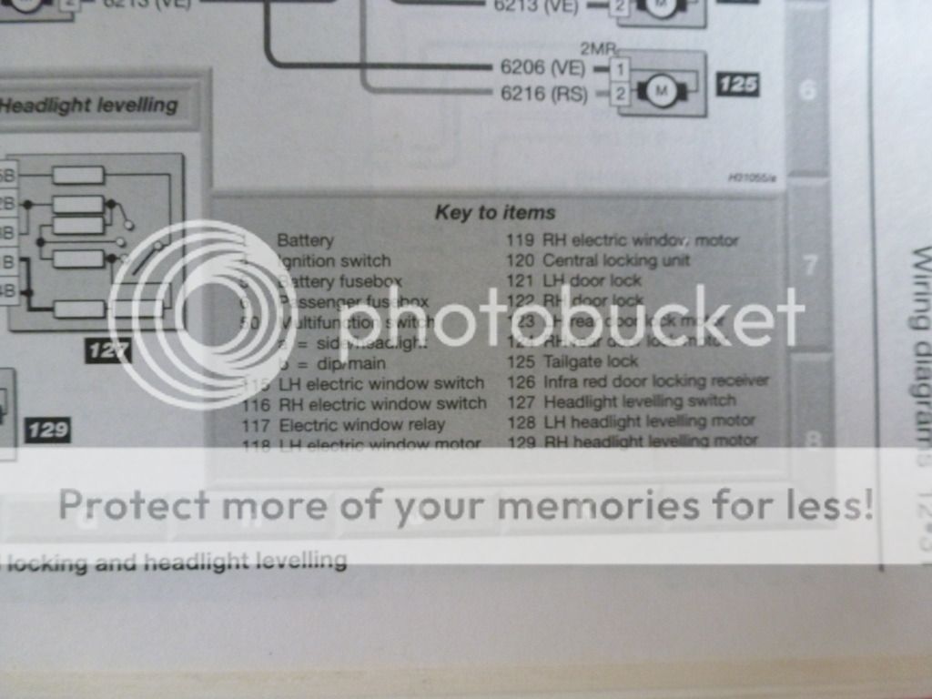
This tends to be an easy step but is time consuming especially if you have just cut enough wire in the loom to extend yourself like I did. Basic wiring applies here and ideally soldering is the key to this conversion lasting. Grab out your Haynes manual and refer to the central locking wiring diagram at the back of the book to keep you on track or simply print the pic I have posted of the wiring diagram below. If like me you need to extend all your wires in the central locking loom, the easiest way of doing this is to cut your new wire into 7 long lengths, so buy at least 10-20m of wire (5 wires for drivers door mech and two wires for the passengers door) Then solder one wire per each wire connecting the loom to the door mech, afterwards you should see something like this below:


Once this is done its now time to identify each new wire, to do this is very simple, grab out your multi meter and put it in continuity mode (beep mode when a circuit is closed) then put the red probe into one of the connectors on the door mech and then with the black probe test each new wire you have made until you hear a beep, once you have this you have located your wire. For example, you need to know which wire was the earth pin, probe the earth wire on the connector and test each wire till it beeps, then label this new wire earth. Once you have established each wire label them according to what is printed on the wire.
E.g. red wire on the passengers door mech is 6012 (R), label this on the new wire so that when you attach it to the main unit you know which pin is
correct.
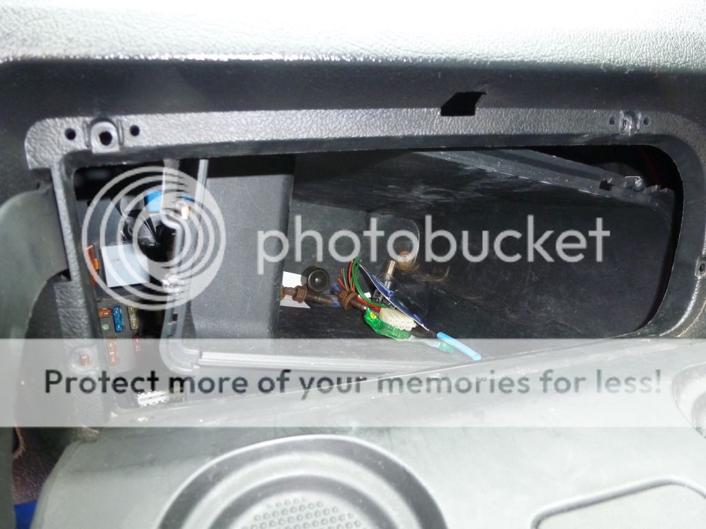
Repeat this process onto the other door, then wrap up all the wires with electricians tape and channel the new wires through the door grommet and to the passengers side foot well, this is where the unit is going to meet and be mounted. Next identify a good constant 12v feed, the best one to use is on the circle harness plug next to the passenger fuse box (the one disconnected to allow you to remove the glove box prior) again always test with multi meter, mine was a chunky pink cable yours might be different so dont follow what cable I used until you have tested. For a good earth this is easy on the same harness you will see another chunky green wire with yellow dots, this wire is standard for earth. Then strip back each chunky wire enough exposure to wrap you 12v on your unit harness to and same with the earth, then solder the tapped wire ensuring the solder has fused through the wire, after soldering give it a good tug to ensure a strong connection, electrician tape or heat shrink the tapped connection to prevent shorts from happening. Now is a good time to wire your inline fuse holder to the 12v feed by snipping the inline fuse holder in half and solder one end to the 12v feed and the other end to your 12v wire going to the unit. Then install the 20a fuse. (As pictured below)
Now going back to you new extended wires prepared earlier for the door mechs, again using the Haynes manual identify which wire goes to which pin on the main unit. If it makes you feel better after joining the wires separate them so no cross contact is made and re screw the two circle harness plugs back to the correct connector on the plate, put your + battery terminal back on and test if you mechs work, if they pop up and back down, then well done, the reason for them popping up and back down is because the mechs cant establish the lock making full grip to your car this is normal when the doors are open. Once you have wired it up correctly solder the new tapped wires together and again insulate them with tape or heat shrink.
Laying new wires

Identifying 12v feed


Main 12v tapped to constant 12v feed

 Step 5: mounting the unit and tidying up:
There is a specific location for the central locking unit and it is located at the rear side top of the passengers fuse box plate, two holes are available for you to screw the unit to the plate, exactly in the same spot as when you extracted it out of the donor Saxo. This is also a good height for signal if its a RF unit, if yours was a IR unit then the IR receiver that is attached to the central lock unit feed it back to where it belongs under the roof lining next to your interior light to get best signal and feed the wires attached to the IR receiver back down the windscreen pillars and to the central lock unit.
Now put your door cards back on, relay the carpet and put everything back how it was. Remembering with the glove box to feed it back up from under the passengers foot well and re screw the retains t 20 screws, then re attach the two circle harness connectors to the loom and re apply your + battery terminal if not done already. Re test your new central locking a good few times to ensure all is working correct, if not for example one motor is getting jammed or a motor isnt working then re investigate what you have done, if it works well done enjoy the freedom of keyless entry!!!
If there is anything you would like to know or need help and assistance please post a message on this thread and be patient and will do my best to answer or get back to you.
Thanks again
Morgiee


 Linear Mode

